Sunday, January 23, 2011

Progress, Jan 22, 2011

Well, today was another day. I took an hour or so to put the journal boxes in place, and that enabled me to get an idea of what this thing really was gonna look like in real life. I'd say this is a huge point in the project because now I can really start to envision the finished product. 3-d models do go a long way, but there's nothing like putting your hands on the actual model to get a sense of size/scale.

Here are the photos from today.


Friday, January 21, 2011

2-8-0 Update, 1/21/2011

Well, this week brought a significant amount of progress!

I was able to machine the frame rails to length, drill the mounting holes for the cylinder mount rails, as well as the rear frame (firebox cradle). In addition, I was able to machine the cylinder mount rails.

I've also assembled the locomotive frame. I learned a hard lesson - don't go to your local ACE/Dickey Bub's, just to buy a certain amount of fasteners. I spent $10 for 20 8-32 flathead screws, and when I got home, I realized I needed 16 per sideframe (for a total of 32), and so I wasn't able to complete it. As a result, I made a stop at Fastenal and picked up a box of 8-32 flathead screws (100 ct) for $8.32! Next time I need a certain amount of fasteners, I'll look up Fastenal!


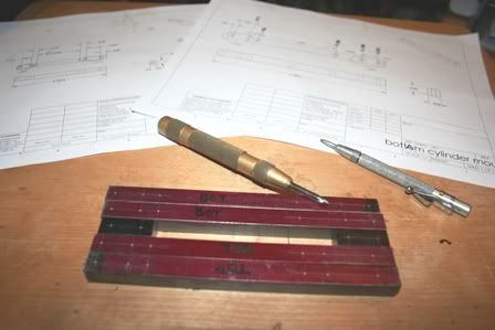
The cylinder mount rails, already laid out and in the process of being center punched


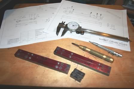
Cylinder mount rails after the holes have been drilled. The Cylinder saddle holes haven't been drilled, as I want to confirm what size bolts I will be using.


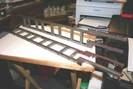
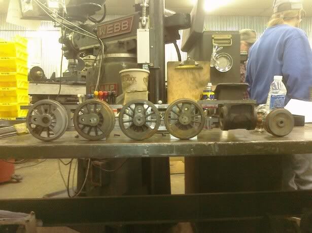
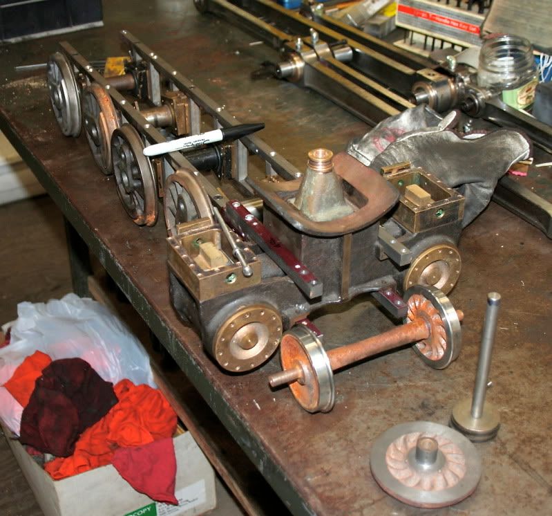
Sideframes assembled!


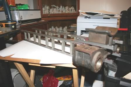
Cylinder saddle in place for the photo!


I've also decided that I may consider new axles for the locomotive, since I want to ensure that they are properly quartered. In conjunction with this step, I'll be re-boring the crankpin holes (probably 0.010" oversize, unless necessary) to ensure they're properly quartered. I don't want to deal with binding drivers later!

So, now my punch list is slightly smaller. The italics indicate that step has been completed.


1) drill holes in top and bottom cylinder mounts
2) machine bottom cylinder mount spacer to length and drill holes.
3) Machine top and bottom frame rails to length
4) Obtain shim stock to install under cylinders
5) Install cylinders (determine size of screws for cylinder mounting, and fabricate if needed)
6) Clean journal boxes and lubricate with grease thoroughly -- Already cleaned, need to be rinsed with acetone/MEK, then lubricated.
a. Install 2 loose bearings with sleeve retainer then do above
7) Drill axles to the bearing races on 2 undrilled axles, tap
a. Cross drill through bearing race if possible….
b. Obtain part number for bearing race for purchase of new ones with through hole if necessary
8) Check fit of journal boxes in the frame
9) Check all drivers for proper quartering. Bore out crankpin holes if needed.
10) Sandblast all drivers
11) Machine new crankpins
12) Order material for pilot support (7/16” x 1-1/2” 1018 speedymetals)
13) Figure out suspension linkage design, send to be laser cut.
14) Construct suspension linkages
15) figure out the rest of the punch list!

Monday, January 17, 2011

Progress on the 2-8-0 Conversion!

After much procrastination, I have finally started working on the Consolidation. I've actually got drawings, and I've actually made chips!

I finally took the time (and had the motivation) to draw most of the parts in SolidWorks. I am still in the process of doing so, but that hasn't stopped me from machining. The first night, I was able to accomplish this:

Photobucket

After some tinkering, and more progress, I finally came up with this:

Photobucket

I have printed all of the drawings to date. If you'll notice, I've temporarily sketched the pilot wheelset to get an idea of location. I also sketched up the pilot deck. For the time being, the drawing shows where the pilot deck will be. I'll finalize those details once I have an assembled frame.

I've also developed the concept for suspension rigging. I just need to order the material and tinker with it. It's a little different, but it will do the job just as well, and will require less effort.

As for machining, I was able to machine the cylinder mounts to length, and will drill the holes accordingly as soon as possible, hopefully this week. If that happens, I'll be able to mount the cylinders to the frame! Thanks to Clayton for rough-cutting the stock to length while I was machining siderod bushings for the WF&P.

I also had an issue with the needle bearings that were installed in the journal boxes. Apparently the needle bearings were all frozen, and had no chance of rolling. I felt that it was likely due to lack of lubrication. I gave one bearing a squirt of WD-40 and let it soak, then worked it for a little bit. The bearing freed up! I also asked Clayton if he'd like a project to work on, and he took on the remaining seven bearings. Now they all roll freely. Unfortunately two were a slip fit in the bores, so I will apply Loctite sleeve retainer and insert the bearing in their boxes after a thorough cleaning with acetone or MEK. This should take care of that problem.

I've also started machining the pilot truck wheels, which just need the tread and flanged machined at this point. I'll machine the axle at some point, but I'm not sure what size to make the axle, as I need to keep the pilot truck in mind. I'll install bronze bushings in the truck for the axle to ride in.

I'll call it quits for the night, but I'll take photos on Wednesday and hope to post them here!
-Mike