Last Wednesday, I machined the eccentric cranks to the print, and the only thing remaining is to cut the clamping slot and those will be done.
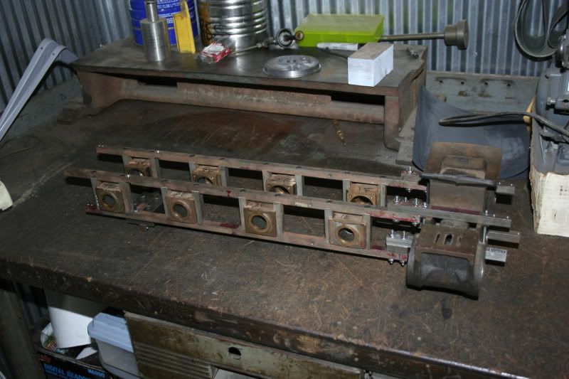
I had lots of binding in the frame rails and cylinder mounts, so I decided to use an endmill to true up the hole locations. Turns out I was off by as much as 20 thousands (by my estimation). I must have done something wrong in the layout and drilling because I didn't think I'd be that far off. The hole was probably slightly crooked. Teaches me to use a cheapo Ryobi drill press! I'll be checking the setup of the table and whatnot before I do any more projects on that.
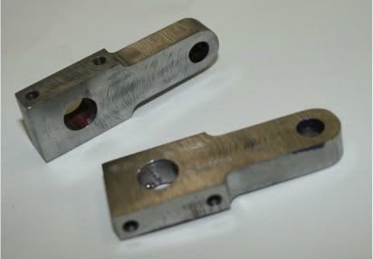
After setting up the mill for the cylinder mounts, I proceeded to remachine the holes so that they were concentric. I used a 3/16" endmill as that is slightly larger than a 10-24 thread. I am using stainless steel studs that I ordered from McMaster (various lengths) for mounting the cylinders and the cylinder mounts along with lockwashers and nuts (18-8 SS). After remachining these, the cylinder mounts bolted flawlessly to the frame. I had to open up the holes on the cylinder itself, but everything is now bolted together.
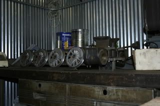
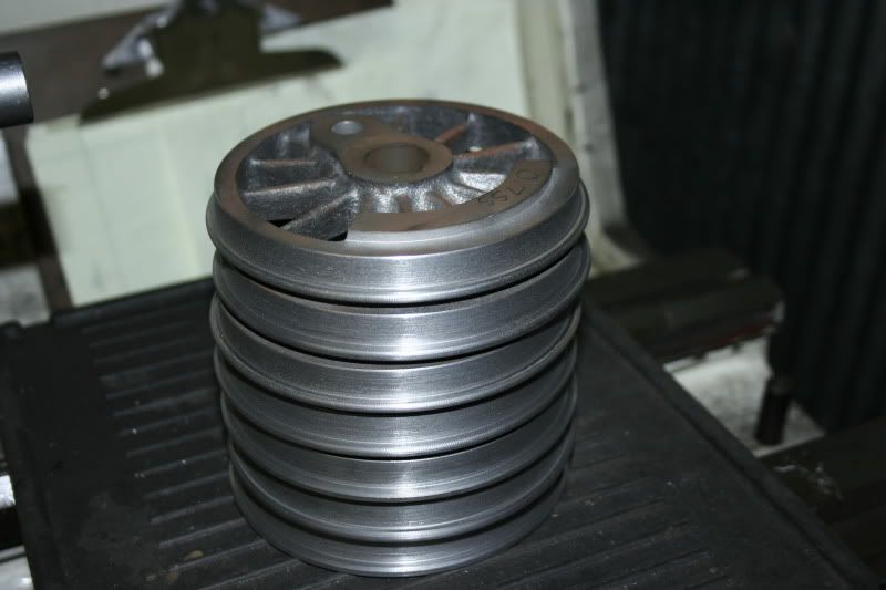
In addition to machining the frame rails and cylinder rails, I also did some driver machining. The two sets of drivers I acquired had different flange diameters and thicknesses, so I decided to set up the lathe and machine them all to the same diameter (flange and tread) and put a 2 degree taper on the tread. Doing this took me less than an hour for all eight drivers, and while I was setting up the lathe for the procedure, I machined the mandrel for the crankpin boring fixture. Talk about killing two birds with one stone!
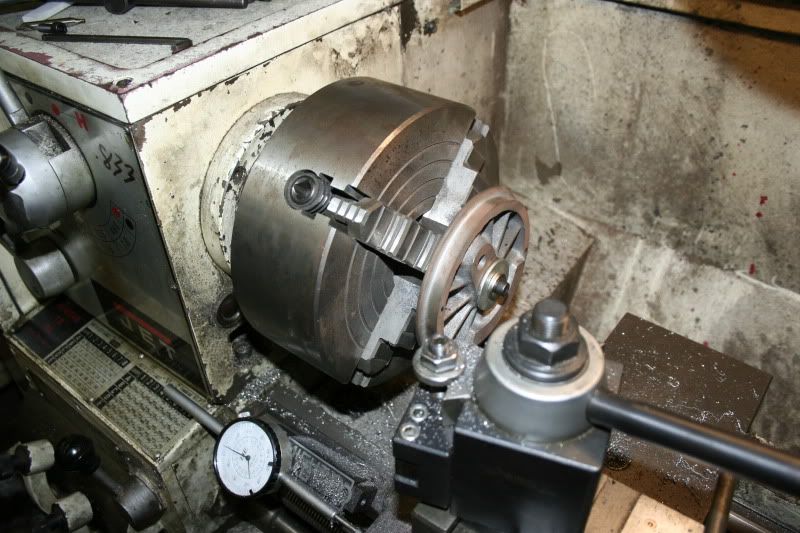
So now I have the mandrel set up in the milling machine ready to re-bore the crankpin holes. I couldn't find the dial indicator that the railroad has so I'll bring it out this Saturday and get it all indicated so she's ready to remachine. If I'm lucky, I'll get it all done this Saturday or Sunday. Worst case, next Wednesday.
So with all that has transpired over the last few days, I am very optimistic about forward progress and plan on proceeding. After I re-bore the crankpin holes, I will make new crankpins that will then be pressed into the drivers. I am debating on if I want to deviate from the blueprints here and go with a male thread on the crankpin so that I can put a castellated nut or a jam nut on the outside (a la prototype). I know castellated nuts would be a pain to create in 1", but worst case, I would put a cotter pin in place. She would still look good and do the job.
After the crankpins are done, I will be ready to press everything together - with the exception of having to put 2 bearings back in the journal boxes, but that should only take a day. That will get me to a rolling frame! After that, I will dabble between suspension components and valve gear components. I have looked at the LE blueprints and am not satisfied with the LE pin designs, as I would feel more comfortable with a shoulder bolt threaded into one side of the fork of the valve gear components. I also plan to use bronze bushings for the valve gear, but I need to find the size I want. I would like to use 5/32 ID, 9/32 OD bushings but will go bigger/smaller if needed.
I've already started thinking/planning out the suspension components, and can't wait to get 'em done! I think construction on that will go fairly quickly as I'll be able to do a setup and machine all of the brackets in one setup relatively quickly.
If anyone has any advice, questions, or simply want to express your interest, please don't hesitate to leave a comment!
See you in the next post!